RELAYGeoscience
Fully integrated structure, trap and seal, geomechanics through to reservoir simulation for oil and gas and carbon capture storage

From producing fields to permanent storage.

Relay Geoscience is a specialist subsurface consultancy. We help operators find and de-risk hydrocarbons more efficiently, and we apply the same disciplines, in the same basins, to make geological storage of CO₂ happen.

Why "Relay"

Our hydrocarbon to carbon capture storage journey.

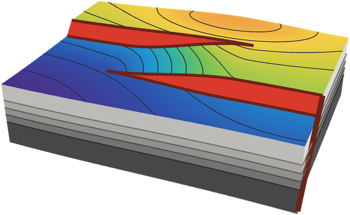
In structural geology a relay ramp transfers displacement between two faults. We took the name because our work does the same thing: the expertise built over decades of oil and gas exploration and production is exactly the expertise that CO₂ storage depends on.

HydrocarbonPropane · C₃H₈
Carbon dioxideCO₂
Oil & gas

Better wells, better portfolios

Every unnecessary dry hole, sidetrack and appraisal well costs capital and carbon. We help exploration and development teams get structure, seal and pressure right before they commit.

  • Prospect de-risking: trap geometry, fault seal, top seal, charge timing
  • Structural review and re-ranking of prospect portfolios
  • New play concepts in mature and under-worked basins
  • Geomechanics for drilling, depletion and late-life operations
Exploration & development
Carbon storage

Containment you can defend

A storage permit rests on the same questions as a prospect, asked in the other direction: will the faults and the caprock hold when pressure goes up rather than down, and for how long?

  • Containment risk: fault reactivation, caprock integrity, legacy wells
  • Geomechanical modelling and safe injection pressure limits
  • Static and dynamic modelling: capacity, injectivity, plume and pressure
  • Depleted-field conversion, from cessation of production to store
Carbon storage
Our mission

Make the transition a subsurface success, not a subsurface surprise.

The world will use oil and gas for decades yet, and every credible pathway to net zero also needs CO₂ stored underground at the gigatonne scale. Both depend on people who understand how rock, faults and fluids behave under changing stress and pressure.

We are mission-led. We want the operators who know their reservoirs best to be the ones who turn them into stores, at the end of field life or alongside production, and we want the hydrocarbons that are still needed to be found with fewer wells. We measure ourselves on the quality of the technical work and on whether it changes a decision.

See where CCS stands today, in numbers

What we do

Specialist disciplines, integrated.

Structural geology

Fault framework interpretation, structural validation and restoration, fault-polygon-consistent mapping.

Geomechanics

In-situ stress and pore pressure, 1D to 3D mechanical earth models, depletion and injection stress paths.

Seal & containment

Fault seal, top seal capacity, fault reactivation and fracture risk under production and injection.

Reservoir engineering

Static and dynamic modelling, injectivity, pressure management, capacity and uncertainty.

Carbon capture & storage

Storage is a containment problem first.

Capture and transport are engineering. Storage is geology, and the regulator's central question is whether the CO₂ will stay where it is put. That question is answered with structure, stress, seal and pressure, which is where we work.

The relay

The same physics, run in the other direction.

A fault that has held a gas column for millions of years has demonstrated a seal at one pressure state. Injection changes that state. Pore pressure rises, effective stress falls, and a fault that was stable through production can move towards failure. In a depleted field the stress path on re-pressurisation is not simply the depletion path reversed.

The method for quantifying this was developed in petroleum geomechanics. Our director was part of the group at the University of Adelaide that introduced ΔP, the pore pressure increase a fault can sustain before reactivation, as a measure of fault seal breach risk, and tested the prediction against CO₂ measured at surface above a natural CO₂ accumulation in the Otway Basin. That is the calculation at the heart of a storage containment assessment today.

For oil and gas companies there is a second relay. Operators hold the wells, the seismic, the production history and the pressure data for the fields best suited to early storage. Planning for storage before cessation of production, rather than after decommissioning, preserves data, infrastructure and optionality. In the EU it is also now an obligation: the Net-Zero Industry Act requires producers to contribute to 50 Mtpa of CO₂ injection capacity by 2030.

What we deliver

Technical work across the life of a store.

Screening

Site screening and ranking

Depleted fields and saline aquifers screened on capacity, injectivity and containment, using the data an operator already holds. Storage resources classified to the SPE SRMS.

Characterisation

Containment risk assessment

Fault and top seal integrity, fault reactivation potential and sustainable pressure limits, fracture and caprock failure, and legacy well exposure, brought into a single risk picture.

Characterisation

Geomechanical modelling

Stress and pore pressure determination from wells, 1D to 3D mechanical earth models, depletion and re-pressurisation stress paths, thermal effects of cold injection near the wellbore.

Modelling

Static and dynamic simulation

Structural and property models built for purpose, then plume migration, pressure build-up and dissipation, injectivity, well count and capacity under uncertainty.

Permitting

Permit and MMV support

Subsurface input to storage permit applications and to measurement, monitoring and verification plans: what to monitor, where, and what a deviation from the model would look like.

Assurance

Independent review

Peer review of storage studies for operators, partners and investors, and technical due diligence on storage licences and projects.

The questions we are asked

What a regulator, a partner or a lender wants to know.

  • Will the bounding faults hold at the planned injection pressure?Fault geometry, juxtaposition and fault rock properties, combined with the stress tensor and pore pressure, give a reactivation pressure for every fault segment, with its uncertainty. The answer sets the operating envelope.
  • How far can the reservoir be re-pressurised?Depletion changes the stress state, not always reversibly. We model the stress path through production and injection rather than assuming the original fracture gradient still applies.
  • Is the caprock a seal to CO₂, and is it intact?Capillary seal capacity for CO₂ differs from that for hydrocarbons. We assess seal capacity, thickness and continuity, and the risk of fracture or fault-related bypass.
  • How much can be injected, how fast, through how many wells?Dynamic simulation of injectivity, pressure interference and plume migration, tied to the geomechanical limits rather than run in isolation from them.
  • What happens at the wells?Legacy wells are often the dominant leakage risk in a depleted field. We map plume and pressure footprints against well locations and barrier status to prioritise remediation and monitoring.
Oil & gas

Structure is where the risk lives.

Understand structure, pressure, fluid migration and seal for the trap before taking the risk. We work with exploration and development teams as specialist support, as independent reviewers, and as a source of new ideas in areas that are thought to be understood.

Prospect de-risking

Trap definition and structural validation, fault seal and juxtaposition analysis, top seal and column height, reactivation and breach risk, and the timing of trap formation against charge. Delivered as a clear, auditable input to the chance of success.

Portfolio review

A consistent structural and seal review across a prospect inventory. Portfolios built over many years by many interpreters carry inconsistent assumptions. We re-rank on a common basis and show which prospects move, and why.

Post-well analysis

Dry-hole and discovery look-backs focused on what the structure and seal prediction got right and wrong, so that the lesson is carried into the next well rather than filed.

Seismic interpretation support

Fault framework and horizon interpretation in structurally complex settings, worked alongside restorable forward models so that the map is geologically defensible as it is built.

Development and late life

Compartmentalisation and fault transmissibility, depletion-induced stress change, fault reactivation and compaction risk, wellbore stability input for infill and sidetrack drilling.

Training

Trap and seal integrity, structural geology for interpreters and applied geomechanics, delivered in-house or through established industry training partners.

New prospects, old areas

Mature basins are rarely as well understood as their well count suggests.

Most mature acreage was interpreted on older data, with the tools and concepts of its time, and the structural model has often been inherited rather than tested. Reprocessed seismic and a fresh structural eye regularly change the answer: a fault that was mapped as basement-rooted is detached; a trap dismissed as breached has a different leak mechanism than assumed; a growth package has been telling the fault history all along and nobody mapped the isopach.

Our approach is to re-examine the structural style first, build a simple three-dimensional kinematic model that has to reproduce the mapped horizons and the thickness variations, and let the misfits show where the interpretation and the geology part company. In our own recent work on the Penola Trough of the onshore Otway Basin, this approach led our director to revise an interpretation he had himself published twenty years earlier, with direct implications for fault seal risk on the surrounding traps.

Near-field, infrastructure-led opportunities found this way are the lowest-cost, lowest-carbon barrels available to an operator. They are also, often, tomorrow's storage sites.

Expertise

Deep in a few disciplines, joined up across them.

We are deliberately narrow. Our core team covers structural geology, geomechanics and reservoir engineering, and we draw on a network of recognised specialists for the tools and disciplines around them. Every deliverable is independently peer-reviewed before it reaches a client.

Structural geology

Fault framework and horizon interpretation on 2D and 3D seismic. Extensional, contractional, inverted and salt-influenced settings. Structural validation by section and map restoration and by kinematic forward modelling. Fault displacement analysis, growth history from isopachs and isochores, relay and linkage geometry, and mapping that honours fault polygons rather than interpolating across them.

Geomechanics

In-situ stress orientation and magnitude from image logs, breakouts, leak-off and extended leak-off tests, mini-fracs and regional data. Pore pressure and fracture gradient. One-dimensional mechanical earth models at wells through to three-dimensional models coupled to reservoir simulation. Stress paths under depletion and injection, compaction and subsidence, wellbore stability.

Fault reactivation

Slip tendency, dilation tendency and critical pore pressure perturbation (ΔP) mapped across three-dimensional fault surfaces in the present-day stress field. Sensitivity to fault rock strength, stress uncertainty and fault geometry. Applied to seal breach risk in exploration, to induced seismicity and to safe injection limits in storage.

Fault and top seal integrity

Juxtaposition (Allan) analysis, shale gouge ratio and other fault rock predictors, calibrated against known columns and pressure data. Top seal capillary capacity, mechanical integrity and the risk of hydraulic fracture. Seal capacity to CO₂ as distinct from hydrocarbons.

Containment risk

Integrated assessment of geological and man-made leakage pathways for CO₂ stores: faults, fractures, caprock, lateral migration and spill, and legacy wells. Risk registers and bow-ties that tie directly to the monitoring plan, consistent with the EU CCS Directive guidance and ISO 27914.

Static modelling

Fit-for-purpose structural and stratigraphic frameworks, facies and property modelling, and uncertainty workflows. Models built so that the fault framework, the geomechanical grid and the simulation grid remain consistent with each other.

Reservoir engineering and dynamic simulation

History-matched depletion models as the starting point for storage in depleted fields. CO₂ injection simulation: injectivity, pressure build-up and interference, plume migration, residual and dissolution trapping, brine production and pressure management. Capacity estimation and classification under SRMS.

Data science and AI

Python-based analytics across well, seismic-derived and production data. Large language models used as an engineering tool to build, test and revise forward models and interpretation utilities quickly, with the rules stated in geological terms and the code open to inspection.

How we assure quality

Peer review is built in, not bolted on.

We are a small firm and we are direct about it. Our answer is to be rigorous about what we take on, to bring in named subject-matter experts where a project needs a discipline or a software platform beyond the core team, and to have final models and reports independently reviewed before delivery. Clients see who did the work and who checked it.

CCS in numbers · compiled September 2026

Thirty years of storage. Three hundred and eighty-three million tonnes.

Geological storage of CO₂ is proven at industrial scale and still a rounding error against what net zero requires. This page tracks where the world, and Europe in particular, stands. Every figure is sourced and dated below.

383MtCO₂ stored underground worldwide, 1996 to 2024London Register of Subsurface CO₂ Storage, 2025
77CCS facilities in operation, 64 Mtpa of capture capacityGlobal CCS Institute, July 2025
734facilities in the global pipeline, 513 Mtpa in totalGlobal CCS Institute, July 2025
≈1Gt/yrcaptured and stored by 2030 in the IEA Net Zero scenarioIEA Net Zero Roadmap, 2023 update

The global picture

Thirty-five key storage projects. Circle area is proportional to published capacity in Mtpa. Select a project for detail.

Capacities are nameplate capture or injection capacity as published by operators, the Global CCS Institute and the IEA; actual injection is often lower (see Gorgon, Sleipner). Locations are approximate. CO₂-EOR projects are included where they report stored volumes.

View all projects as a table

The gap to net zero

If every facility in today's pipeline were built, at every stage of development, global capture capacity would reach roughly half of what the IEA's Net Zero scenario requires by 2030. Only 108 Mtpa is operating or under construction.

The constraint is increasingly storage: characterised, permitted pore space with a defensible containment case.

Where the 383 Mt went

Cumulative CO₂ stored by project, to the end of 2024 unless stated. A handful of large CO₂-EOR and gas-processing projects in the Americas account for most of it. Dedicated saline aquifer storage, the model for most future projects, is still a small share.

Sleipner, the project that started it all in 1996, has stored about 19 Mt.

Europe

50 million tonnes a year by 2030, in law.

The EU Net-Zero Industry Act (Regulation 2024/1735) sets a binding Union target of 50 Mtpa of CO₂ injection capacity by 2030, in storage sites permitted under the CCS Directive, and places the obligation on 44 oil and gas producers in proportion to their 2020–2023 EU production. Permitted capacity in the EU today is about a tenth of that.

Norway, Iceland and the UK are shown for context. Storage outside the EU does not count towards the NZIA target.

Mtpa of injection capacity expected by 2030, by source. "Permitted" is the Commission's March 2026 figure (3.5 Mtpa: Porthos, Prinos, Greensand) plus the Aramis K14-FA/FC permit of May 2026. Operating today: Greensand (0.4 Mtpa, opened 18 September 2026) and the Ravenna pilot.

Who carries the obligation

Contributions are allocated to producers, and so fall by country of production. The Netherlands and Romania together carry almost half of the EU target. Romania holds 20.5% of the obligation against roughly 3% of EU industrial emissions, which makes the Black Sea region one of the most consequential, and least developed, storage provinces in Europe.

The trajectory after 2030

The EU Industrial Carbon Management Strategy sets out what follows: about 280 Mtpa of CO₂ captured by 2040 and about 450 Mtpa by 2050. Europe's theoretical storage resource is not the limit. Appraised, permitted, bankable capacity is.

50 Mtpa
injection capacity by 2030 (NZIA, binding)
≈280 Mtpa
captured by 2040 (ICM Strategy)
≈450 Mtpa
captured by 2050 (ICM Strategy)
>80 Gt
theoretical storage resource, Norwegian shelf
≤78 Gt
theoretical storage resource, UK shelf
≈500 Gt
theoretical, unrisked, across 27 European countries

Country by country

Status at September 2026.

NorwayThree stores operating: Sleipner (1996), Snøhvit (2008), Northern Lights (August 2025). Northern Lights Phase 2 sanctioned to at least 5 Mtpa by 2028. Thirteen storage licences awarded.
DenmarkGreensand opened on 18 September 2026 as the EU's first commercial offshore store, 0.4 Mtpa rising to 4–8 Mtpa. Offshore and onshore exploration licences awarded 2023–24.
NetherlandsPorthos (2.5 Mtpa) under construction, start-up now H2 2027. First Aramis storage permit granted May 2026; five further permit applications filed. Largest NZIA obligation at 13.96 Mtpa.
United KingdomOutside the EU target. Northern Endurance (FID December 2024) and HyNet (financial close April 2025) in construction for 2028. 21 storage licences awarded in 2023; second round closed March 2026. £21.7bn of public support committed.
ItalyRavenna Phase 1 operating at about 25 kt/yr since 2024. Phase 2, 4 Mtpa, in permitting for around 2030.
GreecePrinos storage permit granted February 2026. Phase 1 up to 1 Mtpa, Phase 2 to 3 Mtpa.
GermanyLaw amended November 2025 to permit offshore CO₂ storage and transport. No store yet in permitting. NZIA obligation 5.37 Mtpa.
RomaniaNZIA obligation of 10.25 Mtpa across three producers, the second largest in the EU. Storage framework updated in 2024; no storage permit application yet on the Commission's list.
BulgariaANRAV: capture at the Devnya cement plant with offshore storage in the depleted Galata field, 0.8 Mtpa, targeting 2028 with Innovation Fund support.
PolandLegislation adopted June 2026 widening the areas eligible for onshore storage. NZIA obligation 4.26 Mtpa.
IcelandCarbfix holds the first onshore storage permit under the CCS Directive in the EEA (April 2025), storing CO₂ by mineralisation in basalt.

Sources and notes

  • Global CCS Institute, Global Status of CCS 2025. Facility counts and capture capacity, data to July 2025.
  • London Register of Subsurface CO₂ Storage, 2025 annual report (Imperial College London and partners). Cumulative stored volumes by project, 1996–2024. Includes CO₂-EOR projects that report storage; some volumes are nameplate-based estimates.
  • IEA, Net Zero Roadmap 2023 update and CCUS Projects Database commentary (2024–2026). The IEA counts operating capacity at just over 50 Mtpa on a narrower definition than the Global CCS Institute.
  • European Commission, COM(2026) 252, 28 May 2026: progress report on the NZIA injection capacity target. Permitted capacity, permit applications, producers' plans (29 Mtpa) and Member State reports (33.1 Mtpa).
  • Regulation (EU) 2024/1735 (Net-Zero Industry Act), Articles 20–23; Commission Delegated Regulation (EU) 2025/1477 and Decision (EU) 2025/1479 on obligated entities and contributions.
  • Clean Air Task Force (June 2026) and Bellona, Article 23 Watch 2026: independent assessments of about 43 Mtpa achievable by 2030.
  • European Commission, Industrial Carbon Management Strategy, COM(2024) 62. The 2040 and 2050 figures are capture volumes, for storage and utilisation.
  • Storage resource: Norwegian Offshore Directorate CO₂ Storage Atlas; UK NSTA / CO2Stored; GEUS for CATF (2021) after the EU CO2StoP study. All are theoretical, unrisked estimates.
  • Project details from operator announcements, the NSTA, the Norwegian Offshore Directorate and national authorities. Capture capacity, injection capacity and cumulative stored volume are different quantities and are not summed on this page.
People

A small core team and a network of recognised specialists.

Clients work directly with the people doing the technical work. Around the core team we bring in named experts for specialist tools and disciplines, and for independent review.

Dr Paul Lyon

Dr Paul Lyon

Director · Lead, Structure & Geomechanics

Paul is a structural geologist and geomechanics specialist with 20+ years in exploration and development, including roles with Shell in the Netherlands, Tullow Oil, OMV Petrom in Romania and, most recently, Saudi Aramco. His work has centred on trap definition, fault and top seal evaluation, fault reactivation risk and structural validation across extensional, contractional and inverted basins.

He holds a PhD in structural geology and geomechanics from the University of Adelaide, where he worked on fault seal and fault reactivation in the Otway Basin, including a test of geomechanical fault-reactivation predictions against CO₂ measured at surface above a natural CO₂ accumulation, and a BSc in Applied Geology from the University of Birmingham. He leads the firm's work on AI-assisted structural forward modelling.

Isabel Gutierrez

Isabel Gutierrez

Partner · Lead Reservoir Engineer

Isabel is a senior reservoir engineer with over 10 years of international experience across reservoir engineering, numerical simulation, field development planning and integrated reservoir management. She has worked with major oil and gas organisations and consulting teams on assets across Europe, Africa and South America, with expertise spanning reservoir simulation, history matching, production forecasting, reserves and resources evaluation, uncertainty analysis and development optimisation.

Her career has covered the full reservoir engineering workflow, from field development studies and dynamic modelling to supporting investment and development decisions. More recently she has extended her skill set into data science, machine learning and AI, combining her engineering and industry experience with data-driven approaches to complex problems.

Dr Peter Boult

Dr Peter Boult

Senior Advisor

Peter is a petroleum geologist and an internationally recognised authority on seals. He co-edited the AAPG Hedberg Series volume Evaluating Fault and Cap Rock Seals and the PESA Eastern Australasian Basins Symposium II volume, and has published extensively on the petroleum systems, seal capacity and subsurface plumbing of the Otway Basin.

Expert network

The right specialist, named, for each job.

No small consultancy covers everything, and we do not claim to. We work with an established network of independent experts and specialist firms in fault seal analysis and software, geophysics and quantitative interpretation, petrophysics, well integrity, and monitoring design.

Where a project calls for them, they are brought in by name, with roles and review responsibilities set out in the proposal.

Publications

Published work.

Peer-reviewed papers, conference volumes and conference presentations by members of the team, on fault seal, fault reactivation, structural and seismic interpretation and CO₂ containment.

  • 2026

    Lyon, P.J. Rapid, restorable three-dimensional forward models as part of prospect interpretation: a crestal collapse origin for the Katnook Graben, Penola Trough, Otway Basin.

    In preparation
  • 2019

    Lyon, P.J., Guerra, R., Euranie, L., Stoia, I. and Tyler, E. Offset VSP optimisation in structurally complex settings: an example from onshore Romania. Fifth EAGE Workshop on Borehole Geophysics, The Hague.

    Conference · borehole seismic
  • 2016

    Lyon, P.J., Nicolae, E., Stefaniuc, D., Kallagher, H.J. and Souiki, S. Deepwater geomorphology and seismic facies analysis of the Lower Pliocene deepwater, offshore Romania, Black Sea. AAPG European Regional Conference, Bucharest, 19 May 2016.

    Conference · seismic interpretation · Black Sea
  • 2010

    Lyon, P., Ruckwied, K., Droujinina, A. and Rovira, A. Regional assessment of gross depositional environment for the Lower Cretaceous play, North Caspian. KazGeo 2010, First EAGE International Geosciences Conference on Kazakhstan, Almaty, 15 November 2010.

    Conference · sequence stratigraphy · Caspian
  • 2007

    Lyon, P.J., Boult, P.J., Hillis, R.R. and Bierbrauer, K. Basement controls on fault development in the Penola Trough, Otway Basin, and implications for fault-bounded hydrocarbon traps. Australian Journal of Earth Sciences, 54, 675–689.

    Structure · fault seal
  • 2005

    Lyon, P.J., Boult, P.J., Watson, M. and Hillis, R.R. A systematic fault seal evaluation of the Ladbroke Grove and Pyrus traps of the Penola Trough, Otway Basin. APPEA Journal, 45, 459–476.

    Fault seal · reactivation · CO₂ leakage
  • 2005

    Mildren, S.D., Hillis, R.R., Dewhurst, D.N., Lyon, P.J., Meyer, J.J. and Boult, P.J. FAST: a new technique for geomechanical assessment of the risk of reactivation-related breach of fault seals. In: Boult, P. and Kaldi, J. (eds), Evaluating Fault and Cap Rock Seals. AAPG Hedberg Series 2.

    Geomechanics · ΔP method
  • 2005

    Lyon, P.J., Boult, P.J., Hillis, R.R. and Mildren, S.D. Sealing by shale gouge and subsequent seal breach by reactivation: a case study of the Zema Prospect, Otway Basin. In: Boult, P. and Kaldi, J. (eds), Evaluating Fault and Cap Rock Seals. AAPG Hedberg Series 2.

    Fault seal · reactivation
  • 2004

    Lyon, P.J., Boult, P.J., Mitchell, A. and Hillis, R.R. Improving fault geometry interpretation through 'pseudo-depth' conversion of seismic data in the Penola Trough, Otway Basin. In: Boult, P.J., Johns, D.R. and Lang, S.C. (eds), Eastern Australasian Basins Symposium II. PESA Special Publication, 695–706.

    Seismic interpretation
  • 2004

    Boult, P.J., Lyon, P., Camac, B., Edwards, D. and McKirdy, D.M. Subsurface plumbing of the Crayfish Group in the Penola Trough: Otway Basin. In: Boult, P.J., Johns, D.R. and Lang, S.C. (eds), Eastern Australasian Basins Symposium II. PESA Special Publication, 483–498.

    Petroleum systems · seal
Contact

Bring us the structural problem you are least sure about.

A prospect whose fault seal case is thin, a depleted field being considered for storage, a portfolio that needs a consistent second look, or a structural interpretation that needs an independent test. An initial conversation costs nothing.

Based in

Durham, United Kingdom

Working with clients worldwide.

Company

Relay Geoscience Ltd
Registered in England and Wales, company no. 17424960